A driven earth rod creates an electrode, but it does not automatically make a breaker trip or remove dangerous touch voltage. You will be able to separate the electrode problem from faults in the protective conductor, bonding, protective device, transformer supply or complete fault loop, then specify the tests and documents needed for a safe design.
Key takeaways
- Use a rod in the fault loop, not as a substitute for protective bonding.
- Coordinate fault current, disconnection time and conductor size.
- Specify rod material, length, spacing and tested connection methods.
- Test the complete fault path, not only the rod’s earth resistance.
When an earthing rod is part of the fault-current solution
An earthing rod for fault current provides the return path needed to clear a fault only when the system earthing arrangement makes it part of the intended fault loop.
In a TN installation, the low-impedance protective conductor or PEN conductor normally carries a line-to-case fault back to the transformer, allowing the overcurrent device to disconnect quickly. Soil and a driven rod are not the primary return path.
In a TT installation, electrode resistance forms part of the protection calculation, and an RCD is normally required.
IEC 60364-4-41 gives the TT condition RA × IΔn ≤ 50 V. RA includes the installation earth electrode and protective conductor; IΔn is the RCD’s rated residual operating current. A low electrode reading does not prove rapid breaker operation.
Keep these earthing functions distinct:
- Protective earthing: connects exposed metalwork to the protective conductor.
- System earthing: establishes the supply system’s reference to earth.
- Lightning protection earthing: conducts lightning current safely.
- Functional or instrument earthing: supports equipment operation and noise control.
Bond or separate these functions according to the project design, equipment instructions and applicable standard. Do not connect sensitive instrument earths to random structural metalwork.
A rod can improve the electrode part of the system, but it cannot repair broken bonding, an undersized protective conductor, excessive loop impedance, a wrong breaker or a wrong system arrangement. A rod alone cannot substitute for an RCD, bonding or correctly selected overcurrent protection.
How fault current, disconnection time and conductor size fit together
Prospective fault current is approximately I ≈ U divided by total fault-loop impedance, Zloop. Calculate Zloop from the supply transformer impedance, upstream network, phase conductor, protective conductor or PEN, fault contact, joints and, where applicable, the earth electrode. A low rod resistance cannot offset a high-impedance cable, loose termination or weak transformer source.
| System | Required calculation | Protection check |
|---|---|---|
| TT | Include RA and the protective-conductor path in the fault loop | Verify RCD IΔn, disconnection time and RA × IΔn ≤ 50 V under IEC 60364-4-41 |
| TN | Measure the earth-fault loop impedance at the farthest point | Verify protective-conductor or PEN continuity and breaker operation within the required time |
Compare the calculated current with the protective device’s time-current curve, instantaneous setting and breaking capacity. If the current falls below the instantaneous threshold, use the curve to confirm that thermal or delayed operation still meets the permitted disconnection time.
Check touch voltage during the actual fault; check step voltage as well on larger sites, substations and installations with extensive exposed metalwork. Size the protective earthing conductor with the adiabatic relationship I²t ≤ k²S² from IEC 60364-5-54, where S is conductor area and k depends on conductor material and insulation.
Request a protection-coordination calculation, not a catalogue earth-resistance value. It must show prospective current, clearing time, conductor size, electrode contribution, device settings and commissioning measurements. A long or low-resistance rod cannot compensate for an undersized conductor or a breaker that will not operate at the calculated current.
How to select rods, spacing and connections for the actual site
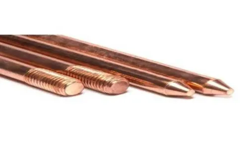
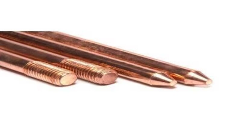
Measured soil resistivity determines the electrode arrangement; do not select a rod from a guessed soil category. Specify base metal, copper coating or galvanising system, minimum coating thickness, diameter, effective length, coating adhesion and resistance to driving damage. Increasing length or reaching a lower-resistivity moisture layer usually reduces resistance more effectively than increasing diameter.
For an industrial earthing rod Pimpri Chinchwad project, define the complete arrangement:
- State each rod’s orientation, burial depth, spacing and interconnection. Closely spaced rods have overlapping current-distribution areas, so their combined resistance will not equal two independent resistances in parallel.
- Connect the electrode to the installation earth bar with a correctly sized earthing conductor, accessible test link and rated clamp, bolted joint or exothermic weld. Protect buried joints against corrosion, inspect them in an inspection chamber, check dissimilar-metal compatibility and verify mechanical driving limits.
- Check thermal withstand for the prospective fault duration using I²t ≤ k²S², then show rods, conductors, joints, test points and dimensions on the drawing. “Two rods” or a claimed resistance is not a design.
| Arrangement | Main benefit | Design caution |
|---|---|---|
| Single deep rod | Reaches lower-resistivity or moist soil | Does not control surface touch and step gradients by itself |
| Multiple rods | Adds electrode area | Use calculated spacing and interconnection; tight spacing reduces the gain from each additional rod |
| Ring or grid | Distributes fault current and reduces touch and step-voltage gradients | Resistance may not fall dramatically below that of one deep rod, but surface voltage control can improve |
A ring or grid can therefore deliver safer performance even when its measured resistance is not the lowest value. Choose the arrangement from the soil report and fault study, not from rod quantity alone.
Why testing a rod is not the same as testing the fault path
A low fall-of-potential reading proves that the electrode has low resistance to the surrounding soil; it does not prove that a breaker will trip quickly. A three-point test measures electrode resistance by moving auxiliary stakes away from the electrode.
The 62% method is valid only when its soil uniformity, electrode geometry and stake-spacing assumptions are satisfied.
1. Record electrode resistance with the three-point method. Use clamp-on or stakeless testing only where a suitable parallel return path exists; it cannot generally measure an isolated single rod accurately.
2. Repeat measurements in representative wet and dry conditions when seasonal moisture affects the design. Excavation, compacted backfill and groundwater movement change soil resistivity, so an installation reading is not automatically the worst-case value.
3. Test and record protective-conductor continuity, earth-fault loop impedance, RCD operating time, bonding resistance and prospective fault current separately. A low electrode value cannot compensate for an open earth bar, faulty test link, loose clamp, failed weld, damaged cable lug or poor transformer connection.
4. Trace the complete path from faulted metalwork to the source, including every joint and the transformer connection. Check touch and step voltages where the installation requires it.
Apply IS 3043, IEEE 80 for substation grounding design and IEC 60364-5-54 for protective conductors and earthing arrangements. Place test records, as-built drawings and the periodic testing schedule in the project file before handover and energisation.
What to demand from an earthing rod manufacturer before purchase
A rod length and an ohmic promise do not show that the installation will clear a fault safely. Give an earthing rod supplier Pimpri Chinchwad enough design data to address the complete fault-current path, not just the electrode.
1. Submit the fault level in kA, protective-device clearing time and settings, system earthing arrangement, prospective installation load, soil-resistivity report, available space, burial depth, corrosion exposure, expected seasonal conditions, and the applicable electrical drawing or project specification.
2. Request a coordinated proposal listing rod material and dimensions, quantity, spacing, interconnections, conductor cross-section, joint method, test points and design assumptions. Reject a generic schedule that omits conductor sizing or protection coordination.
3. Demand batch-specific material certificates, coating or galvanising certificates, coating adhesion and continuity results, dimensional inspection records and product test reports. Verify each document against the delivered batch before installation.
Electrotech Industries can be evaluated as an earthing rod manufacturer in Pimpri Chinchwad by checking whether its quotation addresses these complete fault-loop requirements rather than only rod supply. The manufacturer can correct an electrode or connection-quality problem; the engineer must still correct protection coordination, conductor sizing, system earthing, bonding and device settings.
Require the final acceptance package to include fall-of-potential readings, loop-impedance results, protective-device and RCD tests, bonding checks, as-built drawings and maintenance intervals. These records expose whether the installed electrode, joints and protective path match the proposal and project specification.
Related products
 | Earthing Rod Manufacturer in Pune – Electrotech Industries Electrotech Industries is a leading manufacturer and supplier of high-performance earthing rods,... View product → |
 | Copper Earthing Rod Manufacturer in Pune – Electrotech Industries Electrotech Industries is a trusted manufacturer and supplier of copper earthing rods, designed to... View product → |
Frequently asked questions
When is an earthing rod part of the fault-current solution?
A rod helps clear faults when the system earthing arrangement includes it in the intended low-impedance fault loop. A separate rod that is not bonded into that loop will not reliably carry fault current back to the source.
How do fault current, disconnection time and conductor size fit together?
The protective conductor must carry the prospective fault current until the protective device disconnects. Use the fault current and disconnection time to check the conductor’s thermal withstand, impedance and protective-device coordination.
How should you select rods, spacing and connections for the site?
Base selection on soil conditions, electrode material, required resistance, available depth and expected fault duty. Space multiple rods far enough apart to reduce overlap between their resistance areas, and use connections rated for the conductor and fault current.
Why is testing a rod different from testing the fault path?
A rod-resistance test measures the electrode’s contact with earth. Fault-path verification also checks bonds, protective conductors, joints, source neutral connections and the protective device’s disconnection performance.
What should you demand from an earthing rod manufacturer before purchase?
Request material and dimensions, coating or corrosion details, current-carrying information, connection compatibility, batch traceability, test records and installation guidance for the actual site conditions.
Keywords