A catalogue label such as copper earthing rod does not tell you whether an electrode will work in rocky ground, black cotton soil, industrial fill, or a chemically aggressive plot. By the end, you will be able to convert soil-test data, fault duty, installation constraints, and inspection requirements into a defensible rod specification and procurement decision.
Key takeaways
- Request Wenner four-pin soil resistivity records from each electrode location.
- Select rod construction for soil chemistry, corrosion exposure, and installation method.
- Specify the complete electrode assembly, including clamps, conductors, joints, and access points.
- Compare suppliers using test evidence, installed cost, and delivery commitments.
Start with Soil Resistivity and Fault Duty, Not a Catalogue Resistance
A rod selection starts with measured soil resistivity and prospective fault duty, not a catalogue resistance. Whether you are evaluating an earthing rod manufacturer in Pimpri Chinchwad for projects or another supplier, request Wenner four-pin test records from the proposed electrode locations.
Drive four equally spaced probes in a straight line, inject current through the outer probes, and measure voltage between the inner probes. Repeat the test at several probe spacings and directions; one spacing cannot reveal changes caused by depth, fill, rock, or buried debris.
Request the locations, probe spacings, measured values, soil layers, moisture conditions, and test date.
| Input | Design effect |
|---|---|
| Soil resistivity ρ | Sets approximate resistance |
| Rod length L | Lower resistance by reaching deeper soil |
| Rod diameter d | Influences the logarithmic term |
| Rod quantity and spacing | Controls parallel performance and mutual interference |
| Fault current and clearing time | Sets thermal and safety requirements |
For a uniform soil estimate, use R = ρ/[2πL] × [ln(8L/d) − 1]. Higher ρ raises resistance; greater L lowers it, while increasing diameter has a smaller effect. Layered soil, black cotton soil, rock, fill, or debris requires engineering review rather than blind calculation.
Separate vertical rods by about one rod length before verifying the arrangement. Check conductor thermal withstand, joints, prospective fault current, touch voltage, and step voltage.
One deep rod remains inadequate if resistance, fault-current capacity, or safety-voltage limits fail; use a buried grid or foundation earthing system where the site area, fault duty, or soil profile demands it.
Match Rod Construction to Soil, Corrosion, and Installation Conditions
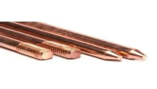
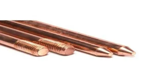
Specify the rod from measured soil and installation conditions, not the label “copper earthing rod.” Solid copper, copper-coated steel, and copper-bonded steel are not interchangeable product names.
| Option | Conductivity and corrosion | Strength, cost, and best use |
|---|---|---|
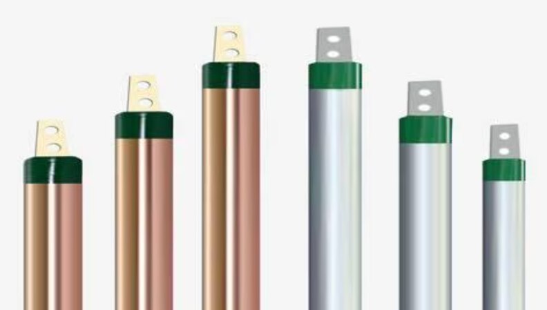
| Solid copper | Highest conductivity; strong corrosion performance, but chemical contamination and stray current can attack it | Weakest for hard driving; highest purchase cost, with lower installation risk in easy ground |
| Copper-bonded steel | Copper carries current and protects the steel core when the bond is continuous | Strong driven electrode; moderate total cost; demand copper thickness, bond-quality evidence, dimensions, and batch traceability—not a copper-colour finish |
| Galvanized steel | Adequate conductivity; zinc protects in non-aggressive soil | Strong and lowest-cost choice for a galvanized-steel network; driving can crack zinc, so specify a driving head and inspect damage |
Rocky ground favours a strong copper-bonded rod or a bored electrode. Black cotton soil demands attention to seasonal movement; filled industrial plots require deeper testing around rubble and variable layers. High moisture, groundwater, chemical contamination, or stray current needs corrosion review before selecting galvanized steel.
A thinner copper rod conducts well but can buckle or mushroom during driving. A stronger rod survives installation and may deliver longer service life.
Worked assumption: 100 Ω·m soil, 3 m by 16 mm rod. R ≈ 100/[2π×3] × [ln(8×3/.016)−1] ≈ 33.5 Ω for one rod. This is not an acceptance value. If resistance, fault duty, touch voltage, or step voltage remains unmet, review extra rods spaced about one rod length apart or a grid with the engineer.
For an industrial earthing rod pimpri chinchwad project, require that review before ordering.
Design the Complete Electrode Assembly Around the Rod
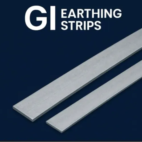
The earthing electrode is the rod; the earthing conductor or GI earthing strip and its approved connector are the parts that connect to it.
- Earthing conductor: cable or strip carrying fault current from the installation.
- GI earthing strip: galvanized-steel conductor used where specified for the network.
- Clamp: approved mechanical connector joining conductor or strip to the rod.
- Coupler: threaded fitting joining rod sections during driving.
- Bonding connection: link between the electrode system and other exposed metalwork.
- Earth pit or inspection chamber: accessible enclosure protecting and exposing the connection for inspection.
Drive or bore the rod vertically with a suitable driving head, not a hammer directly on its thread or end. Protect the joint from corrosion and impact, keep the chamber above finished ground and accessible, and prevent stones, dropped tools, or compaction equipment from damaging it during backfilling.
Coordinate the location with civil drawings, underground utilities, drainage, maintenance routes, and future excavation plans on Pimpri Chinchwad factory plots. In a congested operating plant, staged boring and short sections may reduce disruption; an open construction site may permit longer rods or a wider electrode arrangement.
Do not join copper directly to galvanized metal. Use an approved bimetallic connector, and prohibit unapproved welding or grinding on galvanized surfaces. Never leave a buried joint inaccessible, omit bonding between separate metal systems, or use salt or charcoal as routine backfill; corrosion can follow.
Choose a buried grid, foundation earthing, lightning-protection integration, or engineered arrangement for high fault-current or service-constrained sites when a rod cannot satisfy the duty. Review drawings against IS 3043:2018, project specifications, and utility requirements.
Plan Testing, Acceptance, and Future Access Before Backfilling
A material certificate proves what the rod is made of, not whether the completed earthing system works. Accept the installation in this sequence:
- Inspect the electrode, couplers, clamps, conductor joints, corrosion protection, and inspection chamber before backfilling.
- Test continuity from the rod to the main earthing terminal and each connected conductor.
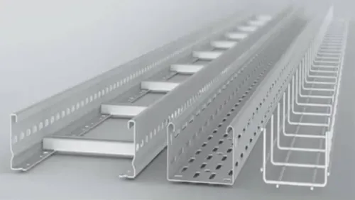
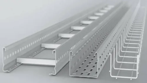
- Check bonding between equipment frames, cable trays, structural steel, pipes, tanks, and other metal systems.
- Confirm that test points remain labelled, accessible, and protected from vehicle or excavation damage.
- Record electrode length, diameter, spacing, configuration, weather, soil condition, instrument and calibration details, auxiliary-electrode positions, and every reading.
Use the fall-of-potential method by injecting test current through a remote auxiliary electrode and measuring voltage through a second probe. The probe positions and site geometry affect the result, so document them and repeat the test when readings are unstable.
Clamp-on testing is not a universal substitute. It works only where parallel return paths exist; an isolated rod or disconnected system cannot provide the closed loop the instrument needs.
In Pimpri Chinchwad, heavy monsoon rain can produce a more optimistic resistance reading than dry-season soil. Define the test condition and retest after major civil work, soil changes, equipment additions, or corrosion findings.
Industrial acceptance also covers fault-current exposure, process-area bonding, lightning protection, touch and step voltage, protective-device operation, and maintenance records. Budget for soil testing, drilling, reinstatement, chambers, clamps, corrosion protection, testing, documentation, and future access. Chemical compound cannot repair poor length, spacing, location, or fault-duty design.
An industrial earthing rod Pimpri Chinchwad project needs engineering evidence, not chemical backfill alone.
Compare Suppliers by Evidence, Installed Cost, and Delivery Risk
Send every bidder the same quotation brief: soil report, single-line diagram, earthing layout, required fault level, electrode schedule, rod material and construction, nominal diameter and lengths, coating or bonding thickness, tip and thread details, compatible coupler and clamp, delivery location, quantity, drawing-approval process, and required test documents.
For a buy earthing rod pimpri chinchwad enquiry, require these procurement records:
- Material and dimensional certificates, coating or cladding evidence, batch identification and traceability.
- Installation instructions, packing protection, replacement policy, delivery lead time, and installation support.
- Completed-system resistance-test reporting, including fall-of-potential method details; a rod certificate alone proves too little.
Compare each delivered rod before installation. Check straightness, diameter and length, permanent markings, coating defects, exposed steel, dents, thread condition, coupler fit, and packaging damage. Quarantine rods with damaged threads or bonding, because forcing a poor joint into service hides the failure underground.
| Option | Evidence and risk | Cost decision |
|---|---|---|
| Local supplier | Faster inspection, site support, and replacement; verify stock and test documents | Lower freight may reduce installed cost |
| Wider supplier | Broader construction choices and capacity; confirm transit protection and response time | Unit savings can disappear through freight, delay, or site labour |
Compare an earthing rod supplier pimpri chinchwad with a wider supplier on technical compliance, inspection evidence, lead time, replacement response, and total installed cost, not unit price. Electrotech Industries belongs in that comparison only when its drawings, material evidence, connection hardware, delivery commitment, and site support meet the engineer-approved specification.
A local address does not prove suitability for an earthing rod manufacturer in pimpri chinchwad for projects.
Related products
 | Earthing Rod Manufacturer in Pune – Electrotech Industries Electrotech Industries is a leading manufacturer and supplier of high-performance earthing rods,... View product → |
 | Copper Earthing Rod Manufacturer in Pune – Electrotech Industries Electrotech Industries is a trusted manufacturer and supplier of copper earthing rods, designed to... View product → |
Frequently asked questions
What should you assess before choosing an earthing rod?
Assess measured soil resistivity at the electrode locations and the prospective fault duty before comparing rod products or catalogue resistance values.
How do soil and corrosion conditions affect rod selection?
Use soil chemistry, moisture, stray-current exposure, and installation conditions to choose the rod construction and corrosion protection required for the project.
What belongs in a complete earthing electrode assembly?
Design the rod with its conductor, clamps or connectors, joints, backfill where specified, inspection chamber, and a practical point for future testing.
How should you compare an earthing rod supplier?
Compare material and test evidence, the total installed cost, delivery reliability, documentation, and the supplier’s ability to support testing and acceptance.
Keywords