Power and control cables need more than a tray that fits their combined width. You need to separate circuits by interference risk, size the system for real loads and bends, and verify that the delivered assembly can be installed, bonded and maintained as specified.
Key takeaways
- Separate VFD, motor and high-current cables from sensitive control circuits.
- Use ladder trays for heavy power cables and perforated trays for smaller runs.
- Size tray width from cable fill, bend radius and future capacity.
- Demand material, coating, load, testing and bonding details in the supplier specification.
Separate power and control cables before choosing the tray
A shared tray is acceptable only after you assess voltage level, circuit function, electromagnetic-interference risk and access requirements. Do not combine power and control cables merely because the cables fit. Sensitive instrumentation, low-level analogue signals and communication circuits deserve stronger separation from motor, variable-frequency-drive and high-current cables.
| Arrangement | Use it when | Main control |
|---|---|---|
| Separate trays | Power cables create magnetic fields, switching noise or heat near instrumentation and communications | Maintain physical separation through risers, equipment entries and supports |
| Metallic divider | Circuits share a route but require continuous segregation | Bond the divider and confirm it remains continuous through bends, tees and transitions |
| Defined crossings | Separate routes are impractical and cables cross only at specific points | Cross at 90 degrees, keep the crossing short, and prevent parallel runs |
Use separate trays when cable functions, voltage classes or equipment owners require independent maintenance. A partition is suitable only when it provides continuous physical separation; a short divider that stops before an elbow does not control interference there. At panels and motors, preserve the same separation instead of merging cables at the final metre.
Define crossings on the layout before installation. Mark each crossing, keep power and control routes perpendicular, and avoid running them together above a riser or inside a crowded entry gland. The industrial cable tray Mumbai specification should show these zones, divider details and bonding points, not just tray width and length.
That detail prevents a quotation from hiding a segregation problem.
Choose ladder or perforated tray for the actual cable mix
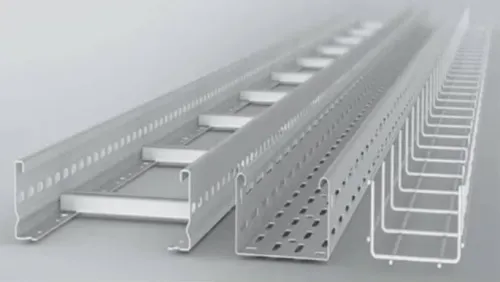
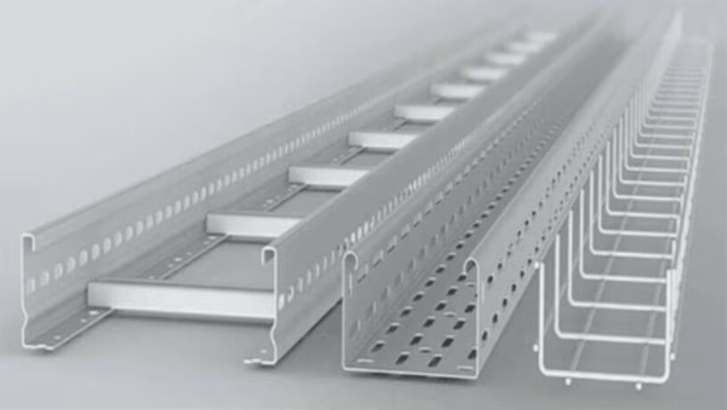
A GI ladder cable tray in Mumbai is preferable for heavily loaded power cables: its open construction improves ventilation, sheds heat and gives frequent cleating points. A GI perforated tray is the safer default when the cable mix includes many small control, instrumentation or communication cables.
| Option | Main advantage | Risk or limitation |
|---|---|---|
| GI ladder tray | Ventilation, power-cable cleating and easy visual access | Small cables can sag, drop between rungs or become difficult to segregate |
| GI perforated tray | Continuous base supports small cables and retains orderly routing | Less open ventilation and fewer natural cleating points for large power cables |
Choose ladder tray for large-diameter feeders, motor circuits and long runs where heat dissipation and cable restraint matter. Secure cables with cleats or approved ties at the specified intervals; do not assume the rungs alone provide support.
Small control cables create problems on a ladder tray when their diameter is less than the rung spacing. They can fall through during pulling, collect at low points and cross into another circuit group. Add a perforated inner tray, divider, close-spaced support, or a cover designed for the system.
Do not use improvised mesh that obstructs inspection or damages insulation.
For mixed runs, use ladder tray for power and a separate perforated tray for controls, or specify a partitioned assembly. Ask the supplier for the tested support span, working load, splice rating and deflection limit; side-rail thickness alone does not prove performance. Check the coating against Mumbai’s coastal air, rooftop exposure or chemical wash-down conditions.
Calculate tray width, bend space and structural load
Start with the cable schedule, not the tray catalogue. Record each cable’s outside diameter, weight per metre, minimum bend radius, quantity and future spare requirement. Apply the occupancy rule in the project standard or applicable code; tray fill is not conduit fill, so a nominal 300 mm width does not prove capacity.
Use this calculation sequence:
- Arrange the cables by type and diameter, then calculate the occupied width and add the specified spare capacity. Check usable depth against the largest cable and any divider or fire barrier.
- Size bends from the largest cable’s minimum bend radius. Extend that requirement through tees, reducers, risers and vertical transitions; a straight tray width cannot provide bend space automatically.
- Add cable weight per metre, tray self-weight, covers, dividers, fire barriers and accessories. Include water, dust or debris where the installation can collect them.
- Select a support span from the manufacturer’s load-span table. Do not apply a 1.5 m or 2 m catalogue rating to a longer span without a structural check.
- Check both uniformly distributed load and concentrated load, such as a person stepping on the tray during installation. Confirm the stated deflection limit and whether the rating covers horizontal, vertical or cantilever mounting.
- Allow for pulling, placing and temporary installation loads. Put supports near bends, tees, risers and splice plates so these fittings do not become lever points.
Request the complete load table, splice arrangement and accessory weights before approving the width. A thinner tray with closer supports can outperform a heavier tray on a longer span.
Write a supplier specification that exposes hidden differences
Reject any quotation that gives only a tray width, thickness and rupees-per-metre rate. A cable tray supplier in Mumbai must price a tested system with defined load capacity, support spacing, finish, joints and every accessory needed for installation.
Request these items with the quotation:
- Material grade, thickness tolerances and material certificates.
- Dimensional drawings showing usable width, depth, hole pattern, bend radius and splice locations.
- Load-span tables stating uniformly distributed working load, concentrated-load limit, deflection criterion and whether the rating applies to horizontal, vertical or cantilever supports.
- Splice-plate design, fasteners, bonding jumpers and the permitted joint resistance or continuity method.
- Galvanizing records identifying pre-galvanized sheet or post-fabrication hot-dip galvanizing, zinc thickness, repair procedure and inspection results.
- Corrosion-finish data matched to coastal salt, chemical vapour, wash-down water, humidity or rooftop exposure; ask for duplex coating or stainless steel where the environment demands it.
- A complete accessory schedule covering bends, tees, reducers, risers, covers, dividers, clamps, hangers and earthing hardware.
- Test reports or conformity documents for the quoted tray and its load claims.
- Factory-cut dimensions and a field-modification procedure requiring zinc-rich repair coating, not ordinary primer, after drilling or cutting.
Whether you compare ELECTROTECH INDUSTRIES with another cable tray manufacturer in Mumbai, place these documents beside the price. A cheaper tray can require closer supports, extra couplers or site-made bends, turning a low metre rate into a higher installed cost.
Related products
 | Cable Tray Manufacturer In Pune – GI Perforated Cable Trays for Reliable Cable Management A trusted cable tray manufacturer offering a wide range of GI... View product → |
 | GI Ladder Cable Tray Manufacturer in Pune – Electrotech Industries Electrotech Industries is a leading manufacturer and supplier of high-quality GI Ladder Cable Trays,... View product → |
Inspect, install and bond the tray system on site
Reject or quarantine damaged sections before installation; bent side rails, crushed perforations and exposed steel will worsen under load and moisture.
An industrial cable tray mumbai specification is incomplete unless it addresses the site atmosphere, not just “GI”: coastal salt, chemical vapour, wash-down water, humid interiors and rooftop exposure can require heavier zinc protection, a duplex coating or stainless steel.
- At delivery, match tray, splice plates, bends, tees, reducers, risers, covers, dividers, clamps, hangers, expansion couplers and bonding jumpers against the approved schedule.
- Check galvanising for bare patches, deep scratches, white corrosion and distortion. Photograph defects and do not conceal them with ordinary aluminium paint or general-purpose primer.
- During installation, keep trays clear of hot surfaces, steam lines, moving equipment and access routes; maintain the specified separation between power and control circuits, plus each cable’s bend radius.
- Use slotted joints or expansion couplers on long runs and where the building structure moves. Support joints, bends and vertical transitions as specified; do not force misaligned sections together.
- Minimise field cutting, drilling and welding. Repair exposed steel with the approved zinc-rich system, following its surface preparation and drying instructions.
- Remove coating only at designated bonding points, or use listed bonding hardware. Bond across every splice, expansion joint, change of direction and painted coupler.
After assembly, use a low-resistance ohmmeter to test continuity end-to-end and across each joint, including movement joints. Record the readings and confirm the tray is connected to the site earthing network; mechanical contact alone proves nothing.
Frequently asked questions
Can power and control cables share one cable tray?
Share a tray only after checking voltage, circuit function, electromagnetic-interference risk and access requirements. Separate instrumentation, analogue and communication cables from VFD and high-current cables when interference is a concern.
When should you choose a ladder cable tray instead of a perforated tray?
Choose ladder tray for heavy power cables, long runs and ventilation. Choose perforated tray for smaller power, control and instrumentation cables that need continuous support and frequent fixing.
How do you calculate the required cable tray width?
Add the cable diameters, apply the permitted fill ratio, and allow space for bend radii, cable cleats, separation and future circuits. Check the tray’s load rating against the cable weight and support spacing.
What should a cable tray supplier specification include?
Specify tray type, material, sheet thickness, finish, dimensions, load rating, support spacing, accessories, corrosion protection, test documents and delivery tolerances.
How do you inspect and bond a cable tray system on site?
Check tray joints, supports, edges, coating damage, cable separation and bend space. Install bonding jumpers across discontinuous joints and connect the tray system to the site earthing network.
Related product
 | GI Perforated Cable Tray Manufacturer in Pune – Electrotech Industries Electrotech Industries is a trusted manufacturer and supplier of GI Perforated Cable Trays, crafted... View product → |
Keywords