A failed facility grounding rod is not confirmed by a single high meter reading: the fault may sit in the clamp, conductor, buried joint, soil, or test setup. By following a controlled inspection, measurement, replacement, and procurement process, you can restore grounding without damaging buried services or accepting an unsuitable electrode.
Key takeaways
- Isolate unsafe equipment before inspecting a suspected grounding failure.
- Test the electrode, connection, and complete grounding system in sequence.
- Trace corrosion, loose bonds, and broken conductors before replacing the rod.
- Match the replacement rod to the installation record and test results.
Recognise a grounding failure and make the facility safe
A possible grounding failure exists when earth resistance rises, a continuity test fails, protective devices nuisance-trip, a person feels a shock, or equipment shows damage linked to fault current. Inspect for loose conductors, corroded connections, broken bonding, and visible damage at the grounding point.
An alarm or trip starts an investigation; it does not prove that the facility grounding rod has failed.
1. Isolate the affected equipment and stop work on exposed conductive parts. De-energise circuits wherever the fault could place people at risk. Do not casually disconnect protective bonding while equipment remains energised; arrange temporary controls approved by the responsible electrical engineer.
2. Issue an electrical work permit, apply lockout/tagout, and verify absence of voltage with an approved tester before testing or repair. Restrict access until the responsible person confirms the controls are effective.
3. Create a recovery record before intervention. Enter the equipment ID, grounding point, fault symptoms, date, weather or soil condition, previous readings, isolation status, and the person who authorised the work.
Do not remove an electrode simply because a reading is high. A buried clamp, corroded joint, broken conductor, changed soil condition, or damaged test link can cause the same symptom. Plan any copper earthing rod replacement only after the conductor, connection hardware, bonding to the grounding network, and mechanical protection are understood.
Salt or charcoal is not a safe shortcut: it can leach away and accelerate corrosion.
Test the electrode, connection, and grounding system in a defined sequence
Start with a visual inspection of the facility grounding rod access point, earthing conductor, strip, clamp, test link, enclosure, and bonding connections. Record looseness, corrosion, broken parts, contamination, water entry, and visible damage before applying test current.
- Use a micro-ohmmeter or suitable continuity tester for the earthing path. Record lead compensation, instrument identification, calibration status, and the exact points tested, such as the main earthing terminal to strip, clamp, and rod connection.
- Under an approved safe-work procedure, disconnect the electrode under test. Use a three-point fall-of-potential earth tester with auxiliary current and potential probes, then move the potential probe through enough positions to demonstrate a stable resistance region. One convenient probe position does not validate the result.
- Use a clamp-on ground tester only when parallel return paths exist and the installation permits this method. Its reading is not equivalent to an isolated fall-of-potential result.
| Instrument | Establishes | Required record |
|---|---|---|
| Continuity tester or micro-ohmmeter | Conductor and connection integrity | Lead compensation and test points |
| Fall-of-potential tester | Isolated electrode resistance | Probe spacing, positions, and stable readings |
| Clamp-on ground tester | Ground-loop current path | Parallel paths and method limitation |
Set pass/fail limits from the facility design, equipment manufacturer instructions, project specification, and governing installation standard, such as the current edition of IS 3043 where it applies. Do not use a universal resistance number. Record electrode isolation, soil condition, every reading, method, acceptance decision, and the responsible reviewer.
A copper earthing rod manufacturer’s data cannot replace the installed-system acceptance record.
Trace the fault before deciding that the rod needs replacement
A failed facility grounding rod is only one explanation for a high resistance reading. Compare today’s continuity and fall-of-potential results with earlier records before approving replacement.
| Result | Likely cause | Next check |
|---|---|---|
| Continuity open, resistance high | Broken conductor, test link, clamp, or buried joint | Trace and inspect the complete path |
| Continuity intact, resistance rises after dry weather | Changed soil moisture or resistivity | Repeat readings under recorded soil conditions |
| Continuity intact, readings vary by probe position | Soil layering, nearby conductors, or overlapping electrode zones | Review probe layout and repeat the test |
Inspect from the main earthing terminal to the electrode. Check the clamp for looseness and corrosion, dissimilar-metal galvanic corrosion, disconnected conductors, broken strips, damaged test links, and poor or water-washed backfill. An intact-looking conductor above ground proves nothing about its buried connection.
Review as-built drawings, cable schedules, inspection photographs, and route markings before locating the electrode. Use an approved cable locator where practical, scan for buried utilities, and never drive a locating bar or replacement rod blindly.
Excavate only under a permit, using hand excavation and trial pits. Provide shoring or battered sides where required, and place barriers around the work area.
If continuity remains intact while repeated fall-of-potential readings change with moisture, investigate seasonal soil-resistivity effects before replacement. Do not add salt or charcoal; it leaches away and accelerates corrosion unless a project engineer has specified controlled soil treatment.
Give the same evidence to an earthing rod manufacturer in Pune when requesting a replacement facility grounding rod.
Replace the electrode without losing the grounding path
Do not remove the old electrode until you know how the grounding conductor will remain connected. A copper earthing rod replacement must preserve protection throughout the work, not simply add a new rod beside the failed one.
1. De-energise affected circuits where the fault could expose people to danger. Issue the electrical work permit, apply lockout/tagout, verify absence of voltage, and install temporary protection approved by the responsible electrical engineer.
2. Expose the connection using controlled excavation. Inspect the conductor, clamp, test link, enclosure, buried joint, and bonding route to the facility grounding network before disturbing the old facility grounding rod.
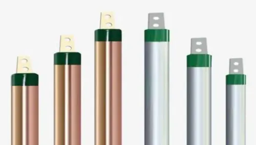
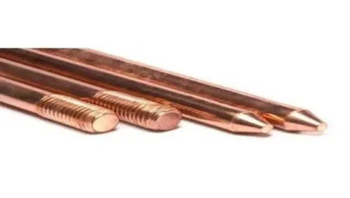
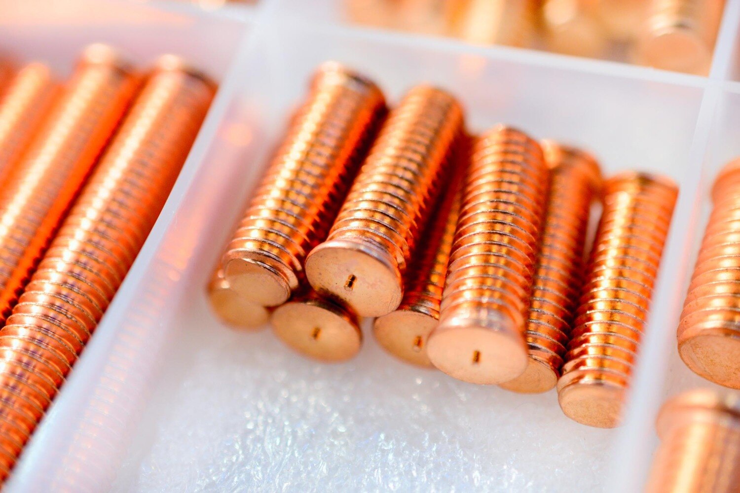
3. Specify the replacement against the design and existing connection system: solid copper or copper-bonded steel, diameter, length, thread, driving point, fault-current duty, corrosion environment, and mechanical load during installation. For a bonded rod, record copper coating thickness, core material, metallurgical bond quality, and test evidence; “copper coated” alone is inadequate.
4. Check the current edition of the governing standard, project specification, and manufacturer data before purchase. IEC 62561-2 applies where the electrode serves a lightning-protection system, while UL 467 evidence applies when required by the project; neither guarantees a particular installed resistance.
5. Remove the old rod only after the conductor and bonding plan are confirmed. Install the new rod at the designed location and depth, use a listed or standards-compliant connector, protect the joint from moisture and mechanical damage, and backfill as specified.
6. Reconnect the conductor, test continuity and earth resistance, verify bonding to the facility grounding network, and record final readings, instrument details, soil condition, photographs, and approval.
Qualify a Pune supplier against the installation record
A recovery purchase must match the installation record, not just the rod’s nominal diameter. Ask every copper earthing rod manufacturer for the factory address, manufacturing process, solid-copper grade or bonded-rod core material, copper coating thickness, dimensions, thread details, driving-point design, batch number, inspection reports, and traceability from the supplied rod to its test records.
- Confirm connector compatibility, fault-current duty, corrosion exposure, warranty terms, packaging, replacement quantities, and support for site questions.
- Request UL 467 listing or test evidence where the project specification requires it. For a lightning-protection electrode, request IEC 62561-2 evidence; neither document guarantees the installed earth resistance.
- Verify who made the rod. A copper earthing rod supplier in pune may be a distributor, while an earthing rod manufacturer in pune must identify its own production records.
Compare suppliers against the existing rod diameter and length, connection hardware, thread, electrode spacing, conductor size, soil conditions, and project specification.
| Supplier category | Evidence to verify | Procurement risk |
|---|---|---|
| Manufacturer | Factory address, process, batch-linked inspection records | Product and records must match |
| Distributor | Original manufacturer, batch traceability, warranty authority | Reseller may not control production |
| Bonded-rod source | Core material, copper thickness, bond test evidence | Correct size can hide a weak coating or bond |
ELECTROTECH INDUSTRIES belongs in the same document-based comparison as other vendors, not in a prequalified category. Close the recovery file with the purchase record, batch details, installation photographs, instrument serial numbers and calibration status, final measurements, soil conditions, and responsible electrical engineer approval.
Related products
 | Copper Earthing Rod Manufacturer in Pune – Electrotech Industries Electrotech Industries is a trusted manufacturer and supplier of copper earthing rods, designed to... View product → |
 | Earthing Rod Manufacturer in Pune – Electrotech Industries Electrotech Industries is a leading manufacturer and supplier of high-performance earthing rods,... View product → |
Frequently asked questions
How do you recognise a grounding failure at a facility?
Check for rising earth resistance, failed continuity, nuisance trips, electric shocks, fault-related equipment damage, loose conductors, corroded connections, broken bonding, and visible damage at the grounding point.
What should you test first when investigating a grounding problem?
Test the electrode, its connection, and the complete grounding system in a defined sequence, recording each result before moving to the next test.
How can you tell whether the grounding rod needs replacement?
Trace the fault through the conductor, connection, bonding points, and electrode before replacing the rod. Replace the electrode when testing identifies electrode damage or unacceptable performance after other faults are ruled out.
How do you replace a facility grounding rod safely?
Install the replacement while preserving an effective grounding path, control the work area, verify the connection, and retest the completed grounding system before returning equipment to service.
Keywords