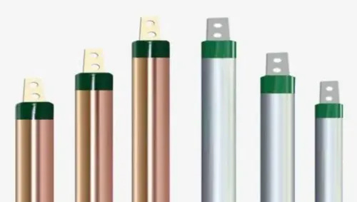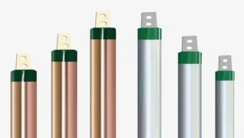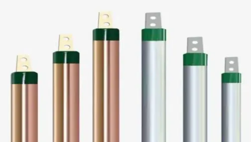
A copper earthing rod connects an electrical installation’s earthing conductor to the soil, giving fault current, lightning current, and surge energy a controlled route away from people and equipment. By the end, you will know where the rod belongs, how it is installed and tested, and what to specify before buying one for a site in Pimpri Chinchwad.
Key takeaways
- Use the rod as a buried electrode, not a normal load-current conductor.
- Add rods when measured resistance remains high or the design requires multiple electrodes.
- Use an approved clamp or exothermic connection and protect it from corrosion.
- Compare rod diameter, length, copper thickness, test results and documentation before ordering.
What does a copper earthing rod do, and where is it installed?
A copper earthing rod is a buried electrode, not a conductor for normal load current. It connects the installation’s earthing conductor to the soil, giving fault current, lightning current, and transient energy a path to disperse while helping control dangerous touch voltage.
Install it vertically by driving or drilling it into the ground beside the relevant installation. Common locations include:
- A building or distribution panel
- A substation or transformer
- A machine area
- A lightning protection system
Keep the rod-to-conductor connection accessible inside an inspection chamber or test point. This allows inspection, retightening, corrosion checks, and retesting; burying the joint permanently under concrete or soil makes fault finding difficult. Use a compatible listed clamp or approved irreversible connection, because a loose or corroded joint can defeat an otherwise suitable electrode.
A visible rod does not prove safe performance, and a continuity reading only shows that an electrical path exists. It does not confirm adequate resistance, bonding, conductor sizing, automatic disconnection, or safe touch and step voltages. Test the completed electrode system using the three-point fall-of-potential method; clamp testing requires a suitable multi-grounded parallel return path.
For a copper earthing rod Pimpri Chinchwad site, soil conditions and the installation design determine whether one rod is enough.
Which type of earthing does the rod support, and when is one rod insufficient?
A copper rod supports several earthing functions, but it does not automatically serve every function or every part of a site.
| Function | What the connection does | Design objective |
|---|---|---|
| Protective earthing | Connects exposed metalwork to the protective conductor | Carry fault current so the protective device operates and supply disconnects automatically |
| Equipment bonding | Joins accessible metal parts and services | Reduce dangerous potential differences between parts you can touch |
| Lightning protection earthing | Provides a controlled path for lightning current | Disperse high impulse current while limiting side-flashing and touch voltage |
| Functional or system earthing | Connects a circuit reference point, such as a transformer neutral, to earth | Stabilise system voltage, manage insulation stress, or support equipment operation |
One rod is insufficient when fault current, lightning current, soil conditions, touch voltage, or equipment design demands more electrode capacity or controlled current paths. The design may require multiple adequately spaced rods, a buried ring, a grid, separate earth bars, or an engineered combination.
Closely packed rods can share overlapping soil-current paths and deliver less improvement than their number suggests.
The electrode is only one part of the safety system. Include correctly sized earthing leads, bonding conductors, suitable protective devices, and automatic disconnection. A search for an earthing rod manufacturer in Pimpri Chinchwad must therefore evaluate the complete earthing arrangement, not copper content alone.
How is a copper earthing rod installed and connected?
Installation starts with a site check, not a hammer. Investigate soil conditions, identify underground services, and select a vertical rod, multiple rods, ring, or grid from the design’s fault-current and voltage requirements.
- Mark the safe work area after service detection. Drill or drive the electrode to the specified depth without bending, damaging, or reducing its continuous copper or copper-bonded surface.
- Expose and prepare the connection point. Remove oxide, dirt, paint, and burrs; keep the electrode and conductor materials compatible. Select a correctly sized listed mechanical clamp or an approved irreversible connection, such as an exothermic weld, for the conductor size, fault duty, and environment.
- Tighten the clamp to the manufacturer’s torque and secure it against loosening. Protect the joint from galvanic corrosion, water ingress, and mechanical impact; copper still needs protection in acidic, saline, contaminated, or stray-current soils.
- Confirm electrical continuity from the earthing bar to the electrode before backfilling. A continuity reading confirms an unbroken path, not acceptable earth performance.
- Route the earthing conductor by the shortest practical protected path. Use a specified conduit or mechanical guard where vehicles, excavation, sharp edges, or vibration could damage it.
- Backfill with clean, specified material and compact it without striking the conductor. Do not casually add salt or charcoal, which can accelerate corrosion.
- Keep the joint accessible inside an inspection chamber. Seal or protect the chamber against water and traffic, and never bury an uninspectable connection under concrete or soil.
If sourcing locally, “copper earthing rod manufacturer Pimpri Chinchwad” is only a search phrase; verify dimensions, construction, connector compatibility, batch traceability, and test evidence.
How do soil conditions, rod dimensions, and testing determine the result?
Soil resistivity, seasonal moisture, electrode material, available depth, fault-current duty, and the design target determine the rod length, diameter, quantity, and spacing. A copper rod does not guarantee a specified resistance.
A longer rod usually reduces resistance more effectively than a larger diameter because it reaches more surrounding soil. Adding rods also helps when they are spaced adequately; closely packed rods share overlapping soil-current paths and deliver less improvement than separate resistance values suggest.
Spacing around one rod length or more is a design starting point, not a pass rule.
1. Measure or assess the site before finalising the layout. Dry, rocky, filled, saline, acidic, or highly variable ground may require deeper electrodes, multiple rods, a ring, a grid, or another engineered solution.
2. Match the arrangement to the prospective fault or lightning current and the required touch and step voltage limits. A deeper rod cannot correct every unsuitable soil condition.
3. Test the completed electrode system with the three-point fall-of-potential method. Use a clamp method only when a suitable multi-grounded parallel return path exists.
4. Record the electrode arrangement, rod dimensions and material, soil and weather conditions, instrument details, test method, and each reading. Ask an earthing rod supplier Pimpri Chinchwad to provide these details for the proposed system.
The design authority must set the acceptance criterion from the current project specification and applicable Indian requirements, including IS 3043 and relevant Central Electricity Authority safety requirements, checked for the installation and project date. A low resistance number alone does not prove safe touch or step voltages, adequate bonding, conductor sizing, or automatic disconnection.
What should you ask a local earthing rod supplier before ordering?
Do not approve a quotation that says only “copper earthing rod.” Ask the earthing rod supplier Pimpri Chinchwad project teams are considering to document the complete electrode assembly:
1. Is the rod solid copper, copper-clad steel, or copper-bonded steel? Request its diameter, length, copper-cladding thickness or minimum copper mass, bond-integrity evidence, batch number, and traceability record.
2. Which standard or certification basis supports the product? Request material and electrical test reports, and check that the evidence applies to the quoted batch rather than a generic product sheet. Compare the documents with IS 3043 and applicable Central Electricity Authority safety requirements.
3. Which clamp or irreversible connector suits the rod, earth-lead material, conductor size, and fault duty? Include clamp material, tightening details, corrosion protection, and evidence for an approved exothermic or other irreversible connection where specified.
4. What else belongs in the supply? Confirm the inspection chamber, test link, earth lead, backfill, sealing arrangement, mechanical protection, and installation conditions, including rocky, filled, wet, or corrosive soil.
5. How will the completed system be tested? Require the proposed three-point fall-of-potential method, or a clamp method only where a suitable multi-grounded return path exists, plus recorded readings and site conditions.
ELECTROTECH INDUSTRIES is one local source to evaluate against those documents, dimensions, connection hardware, and project needs. “Earthing rod manufacturer in Pimpri Chinchwad” and “copper earthing rod manufacturer Pimpri Chinchwad” describe a sourcing route, not compliance proof.
Related products
 | Copper Earthing Rod Manufacturer in Pune – Electrotech Industries Electrotech Industries is a trusted manufacturer and supplier of copper earthing rods, designed to... View product → |
 | Earthing Rod Manufacturer in Pune – Electrotech Industries Electrotech Industries is a leading manufacturer and supplier of high-performance earthing rods,... View product → |
Frequently asked questions
What does a copper earthing rod do, and where is it installed?
A copper earthing rod is a buried electrode that connects the installation’s earthing conductor to the soil. Install it vertically or at the angle specified by the design, with the connection accessible for inspection and testing.
Which type of earthing does a copper rod support?
A copper rod supports pipe, rod or driven-electrode earthing, depending on the electrode design. It provides a path for fault current, lightning current and transient energy into the soil.
When is one copper earthing rod insufficient?
Use additional rods when testing shows the required earth resistance has not been achieved, when soil resistivity is high, or when the electrical design specifies multiple electrodes. Space and bond the rods according to the design rather than assuming that adding one nearby will solve the problem.
How is a copper earthing rod installed and connected?
Drive or install the rod to the specified depth, expose the connection point for inspection, and connect the earthing conductor with a compatible clamp or exothermic weld. Protect the joint against corrosion and mechanical damage.
How do soil conditions and rod dimensions affect earthing performance?
Soil resistivity, moisture, temperature, rod length, rod diameter and electrode spacing affect the result. Test the completed installation with an earth resistance tester and record the reading, test method, date and weather conditions.
Keywords