A facility in Shikrapur can sit on filled soil, weathered rock, clay or compacted construction ground, with moisture changing sharply between monsoon and summer. By the end, you will be able to match soil data, fault-current requirements, corrosion exposure and available space to a rod or electrode arrangement that can be tested and maintained.
Key takeaways
- Measure soil resistivity with a four-pin Wenner survey before selecting the rod.
- Compare copper-bonded steel and GI by corrosion exposure, fault duty and service life.
- Use the electrical design to determine rod length, spacing, parallel paths and quantity.
- Specify accessible test links, labelled connections, inspection records and scheduled resistance testing.
Start with soil data, not the rod material
Measure soil resistivity before choosing an earthing rod for facilities in Shikrapur. Use a four-pin Wenner survey at several points and depths across the plot; one reading near the transformer cannot represent fill, clay lenses, construction debris or weathered rock elsewhere.
Record these site conditions before fixing rod length, spacing or material:
- Dry-season and wet-season resistivity, in ohm-metres
- Soil layers, rock depth, groundwater level and available driving depth
- Filled ground, chemical contamination, buried steel and nearby concrete
- Space for multiple electrodes, interconnecting conductors and inspection pits
- Prospective fault current, protective-device disconnection time, required earth resistance and bonding route
| Soil condition | Design consequence | What to verify |
|---|---|---|
| Drying or layered soil | Resistance can rise after the monsoon or vary sharply with depth | Test at multiple depths and seasons |
| Rocky ground | A driven rod may not reach the planned effective length | Confirm drilling, horizontal electrode or ring-electrode space |
| Fill or contaminated soil | Unstable readings and accelerated corrosion can follow | Map the fill and test corrosion exposure before selecting materials |
Do not approve a rod because its catalogue resistance looks low. The completed system must carry fault current, bond exposed metalwork and limit touch and step voltage until the protective device clears the fault. Poor bonding can leave a dangerous touch voltage even beside a low-resistance electrode.
These measurements give the earthing rod supplier a defensible basis for selecting geometry and quantity. They also prevent a place name, a single test reading or a conductivity claim from deciding the installation.
Copper-bonded steel, GI or another electrode: how to compare them
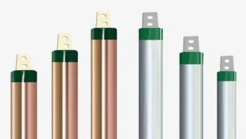
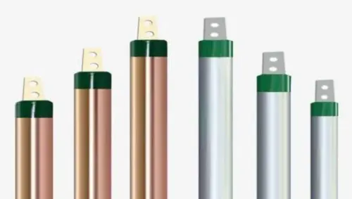
Choose copper-bonded steel when the electrode will remain buried for decades, corrosion exposure is uncertain, or the site uses copper conductors. Its copper layer must be bonded continuously to the steel core; a thin decorative copper plating is not an equivalent product.
| Option | What it means | When it applies |
|---|---|---|
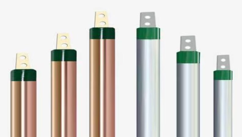
| Copper-bonded steel rod | Steel strength with a bonded copper exterior | Preferred for long service life, variable moisture and installations using copper conductors |
| Hot-dip galvanized steel rod | Zinc-coated steel electrode | Suitable when soil, buried steelwork, clamps and conductors are demonstrably compatible |
| Ring, grid, plate or combined electrodes | A larger or distributed contact area than one rod | Use where rocky ground limits depth, required resistance is low, or the footprint allows a buried network |
The choice is a corrosion and lifecycle decision, not a conductivity contest. A galvanized rod beside copper cable, stainless hardware or aluminium lugs can create galvanic corrosion in wet or chemically contaminated soil unless you specify compatible bimetallic interfaces, clamps and sealing details.
For an industrial earthing rod in Shikrapur, compare the proposed material against the four-pin Wenner soil-resistivity results, fault current, disconnection time, electrode depth and available inspection-pit space. Filled soil, construction debris and seasonal drying can make a single deep rod unreliable; a ring or parallel-rod arrangement may provide better performance.
Require the purchase specification to state copper thickness and bond integrity, zinc coating, core material, diameter, length, straightness, thread dimensions and test standard. Specify the rod-to-conductor connection separately: exothermic welds, listed mechanical clamps and compression connectors have different inspection and maintenance needs.
Match rod geometry and quantity to the electrical design
One rod is enough only when its calculated resistance, fault-current path and safety voltages satisfy the facility design. A low ohmic reading alone is not proof: poor bonding can leave dangerous touch voltage even beside a low-resistance electrode, while protective devices must clear the fault within their specified time.
Use the rod estimate as a design check, not an acceptance result:
R = ρ/[2πL] × [ln(4L/d) − 1]
Here, ρ is soil resistivity, L is rod length and d is diameter. Increasing length usually reduces resistance more effectively than increasing diameter. Confirm the choice against:
- The maximum earth resistance set by the power system, equipment and protection study.
- Prospective fault current and the conductor’s thermal withstand until the breaker or fuse disconnects.
- Touch- and step-voltage limits, including bonding to equipment frames, structures, cable trays and the main earthing terminal.
- The available depth, rock layers, buried services and space for an accessible inspection pit.
Add rods when one electrode cannot meet the design or when the fault-current path needs additional capacity. Do not divide the first rod’s resistance by the number of rods: overlapping soil-resistance zones reduce the benefit. Start spacing at about one rod length or more, then verify the arrangement by calculation and field testing.
If Shikrapur’s footprint cannot provide that spacing, an earthing ring or grid may outperform a dense cluster of short rods. Keep each electrode identifiable and connected through a test link that remains accessible after paving or landscaping.
Specify the connection, inspection and procurement details
Approve the rod only as part of a documented earthing assembly. Whether you buy from ELECTROTECH INDUSTRIES or another earthing rod supplier in Shikrapur, require the supplier to link the proposed material and dimensions to your four-pin Wenner soil-resistivity results, fault current, disconnection time, corrosion exposure and inspection-pit layout.
1. Specify the rod-to-conductor connection separately. Name the connection method: exothermic weld, listed mechanical clamp or compression connector. Require its conductor-size range, material compatibility, installation torque or weld procedure, corrosion protection and inspection method. Reject hardware-store clamps and concealed bolted joints that are unrated or impossible to inspect.
2. Demand traceability for every delivery. The supplier’s documents should identify the mill or batch, rod diameter and length, steel core, copper or zinc coating, threaded accessories and manufacturing date. Ask for coating-thickness, adhesion, tensile-strength and applicable salt-spray or corrosion-test evidence. Require continuity evidence from the rod body through couplers and threaded fittings.
3. Make the bill of materials explicit. It should name compatible clamps, bimetallic interfaces, sealants, stainless hardware, conductor lugs, test links and above-ground termination parts. Do not bury copper-to-galvanized-steel, aluminium-to-copper or stainless-to-galvanized joints without a stated corrosion-control detail.
4. Require a drawing showing rod spacing, conductor route, pit dimensions and test access. Untraceable rods offered only on a low price are a procurement failure, not a saving. Reject substitutions unless the supplier submits revised evidence and your designer approves them.
Related products
 | Earthing Rod Manufacturer in Pune – Electrotech Industries Electrotech Industries is a leading manufacturer and supplier of high-performance earthing rods,... View product → |
 | Copper Earthing Rod Manufacturer in Pune – Electrotech Industries Electrotech Industries is a trusted manufacturer and supplier of copper earthing rods, designed to... View product → |
Test the installed system and plan for its service life
Do not accept a low resistance reading from one test point as proof of safety. After installation, verify conductor continuity from each rod to the main earth bar, measure electrode resistance using the three-point fall-of-potential method, and confirm that fault-loop impedance allows the protective device to disconnect within the design time.
A clamp meter alone cannot prove an isolated electrode’s resistance.
Use this acceptance checklist:
- Inspect every rod-to-conductor connection for the specified exothermic weld, compression connector or listed clamp; reject loose, concealed or untraceable joints.
- Record electrode resistance, loop impedance, test current, instrument serial number and calibration date.
- Check exposed metalwork for continuity to the earth bar and investigate unexpected touch-voltage readings.
- Compare results with the design values and retain signed test reports with photographs.
A search for an earthing rod manufacturer in shikrapur for facility owners should also cover maintenance, not just delivery. Keep each earth pit accessible, label every electrode, protect the riser from vehicles and water damage, and preserve an as-built drawing showing rod locations, depths, conductor sizes and connection points.
Inspect pits, links and above-ground conductors after a major fault, lightning event, excavation or electrical modification, then repeat the scheduled resistance and continuity tests. Rising resistance, rust at a joint, damaged covers or a missing test link requires investigation before the system is relied upon again.
Frequently asked questions
Why measure soil resistivity before choosing an earthing rod for a Shikrapur facility?
Soil resistivity reveals changes caused by fill, clay, construction debris, weathered rock and seasonal moisture. Take four-pin Wenner readings at several points and depths instead of relying on one transformer-area reading.
How do copper-bonded steel and GI earthing rods compare?
Compare coating thickness, steel strength, corrosion exposure, fault-current duty, expected service life and compatibility with the conductor and clamps. GI can suit compatible installations, while copper-bonded steel provides a copper exterior on a steel core.
How do you determine earthing rod length and quantity?
Use the measured soil resistivity and the electrical design target to select rod geometry and quantity. Check rod spacing, parallel conductors, fault current, touch voltage and step voltage rather than choosing a rod from length alone.
What should you specify when buying an earthing rod from a Shikrapur supplier?
Specify material, diameter, length, coating or galvanising details, threads, couplers, clamps, conductor size, test links, inspection access, labels, certificates and traceable batch information.
How do you test and maintain an installed earthing system?
Test the completed system with an appropriate earth resistance method, record soil and weather conditions, inspect accessible joints and test links, and repeat testing on a planned schedule after modifications or faults.
Keywords